Building First-Version In-Mouth Rein Pressure Sensors
Before we get onto the topic at hand, following on from the previous post, a few more thoughts on how the pressure can be measured for the mechanical horse:
1. Measure the deflection of the horse body as an alternative method of measuring the pressure, e.g., using ultrasonic range measurements or LIDAR to map the deformation of the body to determine the location and magnitude of applied pressure.
2. Use a sock or similar pre-made (or partially pre-made) container/sleeve into which the sensor(s) can be inserted for safety/holding together and/or ease of attachment.
3. Use a single resistor in-line with the sensor, to increase the range of measurement.
4. Switch between different values of in-line resistor to improve the sensitivity at different pressure ranges. This is because the sensor is effectively being used as a voltage dividor made of the sensor and another resistor. The greatest change in voltage occurs when the other resistor is of similar resistance to the sensor.
In fact, (3) and (4) above have helped me to refine the design, including to overcome an issue where the foam does not always bounce back elastically, but can rest in a position with decreased resistance -- especially at high temperatures (it was 41C here today). Using a 10M Ohm resistor in line has greatly increased the range of values I can read at lower pressures. At higher pressures, the resistance drops below 1M Ohm, so we have less than 10% of the dynamic range of the sensor available to us. By switching to, say, a 1M, 100K or even lower value resistor, it should be possible to have a "second gear" that has a wide range of voltages over a particular pressure range.
If I carefully arrange the analog switches, I could switch between different resistors using one, and then between different sensors with another, thus allowing high dynamic range of readings with relatively few components.
I'll certainly have to give that a go.
But first, I want to make a couple of smaller sensors that can fit in the back of the mouth of the head, so that I can rig them up as a rein pressure sensor, and see how that behaves. It's the end of a long day, so a bit of "arts and crafts" building the sensors is probably a good use of the time. I can then revisit the analog switching and other fancier bits, like implementing the mains noise cancellation, over the weekend when I will hopefully have more time and energy.
For these smaller sensors, I am using one of the ideas from the previous brain-storming session: Putting both copper tabs at one end, so that the sensor is sensitive right to the very end at the other end.

Working on these, I was reminded of something I had observed earlier: If the fence ribbon is curved, it can make a stronger connection when idle than is ideal. By bending the sensor until the fence tape straightens out a bit helps this quite a lot.
I am also going to stitch these two sensors together into the one little pouch, so that it is easier to position them in the back of the mouth:


All done:

Interestingly testing them shows some cross-activation, i.e., squishing one results in a weaker but still detectable effect on the other. I'm assuming that this is due to the combined pouch warping and the tightness of the fabric conducting some of the pressure. Anyway, it doesn't look like it will be enough to be a problem.
I think the next step is for me to design up the circuit to allow selection of in-line resistor values (for increasing the dynamic range of the sensor), and selecting which sensor is to be routed through.
The design will be based on six idential units like this, which allow connecting any of the four in-line resistor values (or actually, any combination of them), to any of the four sensors on that group (or again, any combination of them):

Six groups times 4 sensors = 24 sensors, as previously discussed. The ability to connect multiple sensors together is likely to be useful, as it will allow scanning a group of sensors quickly to check if any of them have pressure, as it will effectively read the combined value. This could be handy, e.g., to check if there is any pressure on the set of leg sensors on one side. If there is, then the position of the leg pressure could be checked, but other wise we wouldn't waste the time checking.
I would like this to all fit on a normal sized Arduino "Shield" sized PCB, so I did a quick fit test:

I know some folks will cringe at my use of both hole-through and SMD components, but I think it makes sense here: The SMD ICs are of an outline that is quite easy to solder by hand, and of course the hole-through resistors and connectors are very simple to solder by hand. So the whole board will be very easy to assemble by hand. On the flip side, using the SMD ICs allows the total size to be kept to the Arduino shield size. It is still rather dense, so it will be seen whether I can actually route the board with this density, but it should be possible -- especially if i put some of the ICs on the reverse side of the board. If you are re-flowing a board, that's a bad idea, but for hand-soldering, its not a problem.
But before I put any effort into routing the board, we need to check that the circuit itself will work. For that, I have an Arduino Shield prototyping board onto which I can hand-solder hole-through components enough to make one (or maybe two) sets of sensor inputs:

So time to do a bit of soldering and assembly...
Let's get the netlist sorted, so that I know what I am doing, and can assemble it as quickly and error-free as possible:
5V - IC pin 14 on all ICs, high-side of all resistors
GND - IC pin 7 on all ICs, bottom-side of all sensor inputs
A0 - U1 pins 2,3,9,10, U2 pins 1,4,8,11
A1 - U3 pins 2,3,9,10, U4 pins 1,4,8,11
U2 pin 2 - Sensor 1 top
U2 pin 3 - Sensor 2 top
U2 pin 9 - Sensor 3 top
U2 pin 10 - Sensor 4 top
U4 pin 2 - Sensor 5 top
U4 pin 3 - Sensor 6 top
U4 pin 9 - Sensor 7 top
U4 pin 10 - Sensor 8 top
U1 pin 1 - 10M Ohm Resistor R1
U1 pin 4 - 1M Ohm Resistor R2
U1 pin 8 - 100K Ohm Resistor R3
U1 pin 11 - 10K Ohm Resistor R4
U3 pin 1 - 10M Ohm Resistor R5
U3 pin 4 - 1M Ohm Resistor R6
U3 pin 8 - 100K Ohm Resistor R7
U3 pin 11 - 10K Ohm Resistor R8
U1,U3 pin 13 - Arduino D4
U1,U3 pin 5 - Arduino D5
U1,U3 pin 6 - Arduino D6
U1,U3 pin 12 - Arduino D7
U2,U4 pin 13 - Arduino D8
U2,U4 pin 5 - Arduino D9
U2,U4 pin 6 - Arduino D10
U2,U4 pin 12 - Arduino D11
It's all assembled now, and I have also put some 2x1 .1" header pins on the end of the two sensor connectors for the mouth sensor, to make it easier to plug them in and move them around:


Initial testing shows that I can read the sensors, which is good. However, it seems that all four sensor ports are connected together. Have I messed up the netlist, or have I assembled something incorrectly, or mis-read the datasheet?
Double-checking the datasheet, the enable lines are active-high, so first step is to make sure that I am controlling those pins on the Arduino correctly... and apparently I am not: They are all showing +5V, even when I have only one of them set high.
With that fixed, it now more or less works. These kinds of hand-prototyped boards with lots of blue wire are prone to short-circuits where the blue insulation on the wires melts in places you don't intend it to, or don't make a good connection somewhere. I'm actually really pleased that it worked first time, without requiring any remedial soldering etc, meaning that both my design was not defective, and that I didn't mess up the fiddly build too much. So while I am seeing some issues, the overall concept is working quite well: I have two sensors on one multiplexed channel, and am able to read them. There is a bit more cross-talk between the signals than I would like, but its within liveable limits.
I can also fairly easily change the resolution by selecting the resistor. Interestingly, it seems that 1MOhm instead of 10MOhm is probably a good all-round setting: The reduced resistance results in increased current and increased noise immunity as a result.
So I think I am now at the point where I can write a little program that will read the output from the sensor, and determine the relative force on the mouth, as well as the direction (or rather, the imbalance in force between left and right sides of the mouth).
Working on that program, I'm now having to think about how to best interpret the sensor data: Is it just force on each side vs some estimate of what the maximum force might be? Or do I need to do something more subtle where I track the force over time and care more about changes in force, rather than absolute measures?
Comparing current force on each side vs the maximum force seen on each side results in a rather erratic result -- and increasingly so if I revise the max and min forces seen over time, to maintain a rolling window to exclude one-off spurious transient signals.
It might be possible to moderate this effect by having a minimum total force range, so that when the sensors are idle, we don't progressively amplify the apparent input. Yes: That seems to help quite a lot.
Now to make it give me a nice visual indication of the direction and force on-screen. Something like this maybe...
[################## ] : [ <<<<<<<< ] : 41/100, 66/100 -33/84
[################# ] : [ <<<<<<< ] : 39/100, 62/100 -34/83
[################ ] : [ <<<<< ] : 38/100, 57/100 -35/82
[############## ] : [ <<< ] : 37/100, 48/100 -35/81
[############## ] : [ << ] : 37/100, 45/100 -35/80
[############### ] : [ << ] : 40/100, 49/100 -36/79
[################ ] : [ <<<< ] : 42/100, 55/100 -37/78
[################ ] : [ <<<< ] : 42/100, 57/100 -38/77
[################ ] : [ <<< ] : 42/100, 53/100 -39/76
[############### ] : [ << ] : 42/100, 50/100 -40/75
[############## ] : [ < ] : 41/100, 45/100 -41/74
[############## ] : [ ] : 41/100, 42/100 -42/73
[############# ] : [ > ] : 41/100, 38/100 -43/72
[############ ] : [ >> ] : 40/100, 32/100 -44/71
[########## ] : [ >>>>> ] : 39/100, 21/100 -45/70
[######### ] : [ >>>>>> ] : 38/100, 15/100 -46/70
[######## ] : [ >>>>>> ] : 36/100, 8/100 -45/71
[###### ] : [ >>>>>>> ] : 34/100, 2/100 -44/72
[###### ] : [ >>>>>>> ] : 34/100, 3/100 -43/73
[####### ] : [ >>>>>> ] : 35/100, 5/100 -42/74
[####### ] : [ >>>>>>> ] : 37/100, 6/100 -42/75
[######### ] : [ >>>>>> ] : 41/100, 14/100 -43/76
[############ ] : [ >>>>> ] : 45/100, 28/100 -44/75
[############## ] : [ >> ] : 46/100, 39/100 -45/74
[################ ] : [ ] : 48/100, 51/100 -46/73
[################## ] : [ <<<<< ] : 48/100, 63/100 -47/72
[################### ] : [ <<<<<<< ] : 48/100, 67/100 -48/71
[##################### ] : [ <<<<<<<<<<<< ] : 49/100, 78/100 -49/70
[###################### ] : [ <<<<<<<<<<<<<<< ] : 50/100, 83/100 -50/69
[##################### ] : [ <<<<<<<<<<<<< ] : 50/100, 80/100 -51/68
[#################### ] : [ <<<<<<<<< ] : 50/100, 72/100 -52/67
[################## ] : [ <<<< ] : 49/100, 61/100 -53/66
[################# ] : [ << ] : 49/100, 57/100 -54/65
[################# ] : [ < ] : 50/100, 54/100 -55/64
[################## ] : [ < ] : 51/100, 56/100 -56/63
[################## ] : [ < ] : 53/100, 58/100 -57/62
The #'s on the left indicate the degree of force detected by adding the reading from both sensors, while the <'s and >'s indicate which direction overall the mouth is being pulled, with more <'s or >'s meaning that the bias to that side is stronger.
I installed the mouth sensors into the horse, and did a bit of testing with it.
First, I had to remove some of the black leatherette from the muzzle, as it was just a bit too tight in the mouth to get the sensor. The sensor is also wrapped in black leatherette, so it's a bit hard to see here that it is installed -- apart from the tell-tale wires hanging down through the chin:


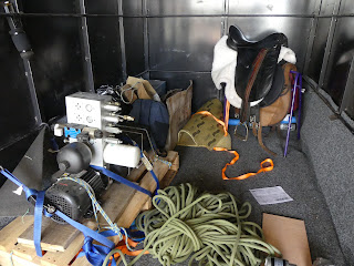
Then it was time to setup my make-shift "work station" in the sand pit:


1. The hinge in the middle of the bit pushes on one or the other of the sensors, causing that sensor to read strongly whichever side the reins are pulled.
2. The pressure on the sensor from the reins is quite low much of the time, except for on the hinge-point.
3. The update rate from the sensor is a bit too slow.
To fix (1) and (2), I'll rearrange the sensors in the mouth to have a large gap between them, big enough for the hinge of the bit, and also so that the sensors stick slightly out each side of the mouth, so that they will receive more compressive force when the reins are tensioned.
To fix (3), I can just tell the Arduino program to only check 1 of the 6 analog lines for now, to get a 6x speed up.
Meanwhile, today was horse riding lesson day, so I showed Maree, my riding instructor, the progress on the sensors. She noticed what I had already noticed, that the foam in the sensors provides a fairly credible horse-mouth kind of feel -- certainly enough for it to be usable in rider education after some refinement. I'll likely try to make a stand-alone horse head with the Arduino to make a simple rein tension trainer for riders, so that they can practice maintaining smooth pressure, and balancing the force between the left and right.
Related to that, I need to also improve the software for reading the sensors to handle the fact that the sensors are not, and basically cannot be calibrated, so they can end up with a steady bias in one direction or the other. This is all fine and solveable, because we really care about the impulse to the left or the right, and having fairly steady pressure most of the time, rather than measuring pressure exactly. It does just require some more sophisticated signal processing.


Comments
Post a Comment