Head rotation hinge and test setup
Having worked out that I need to add cheek pressure sensors to detect open reins, and that the motion of the head when asking for the horse to turn the head affects the felt pressure on the reins, I am now turning to allowing the head rotate in a more robust manner. At the same time, I want to make a detached head setup, so that I can easily test the reins interaction from on the ground, without having to mount the "horse".
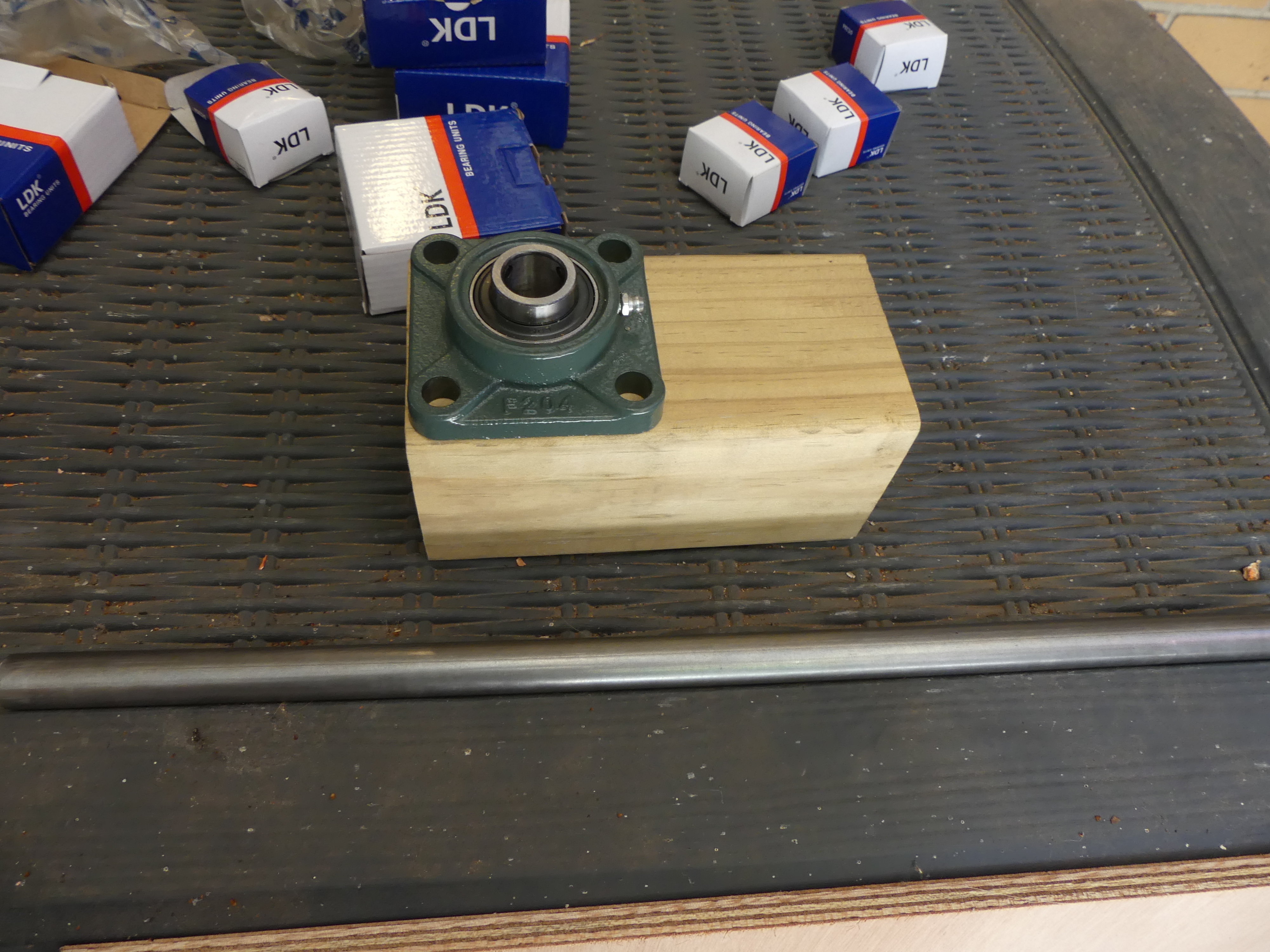
The first step was to think about what I was going to do for the hinge. So I went out to CBC Bearings at Regency Park and had a chat to the nice folks there, complete with wooden horse head on their counter. They were very helpful, and we settled on using some nice heavy-duty bearings that take a 20mm steel shaft, to make sure that the weight and forces of the heavy horse head moving are easily accommodated without risk of self-damage etc.
The steel shaft I purchased from METALCORP on Grand Junction Road, who were also really helpful. It turns out the woman who served me has horses, so we had a good chat about what I was doing. This is what I ended up with as starting point:

(I did also visit a hydraulics place, but got a rather disinterested and unhelpful customer experience. I think the poor guy drew the short straw for working the Saturday morning of a long weekend when he really wanted to go fishing. But the hydraulics power pack I bought has arrived, so I'll do a post on that soon, too.)
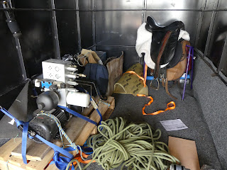
Back to the hinge... It is made of bearings on the top and bottom of the neck mount, and then on the extension of the "spine". These are beefy almost steam-punk looking things:


A quick fit testing on the piece of neck (which will be attached to the head using a hinge):


Then with it attached to the marine ply:


I'm glad I made the shaft longer than I thought I would need, as I need almost every bit of its 500mm length to clear the ground, when the head is fully lowered, which it will be for a while, until I build the actuator to pull the head up:
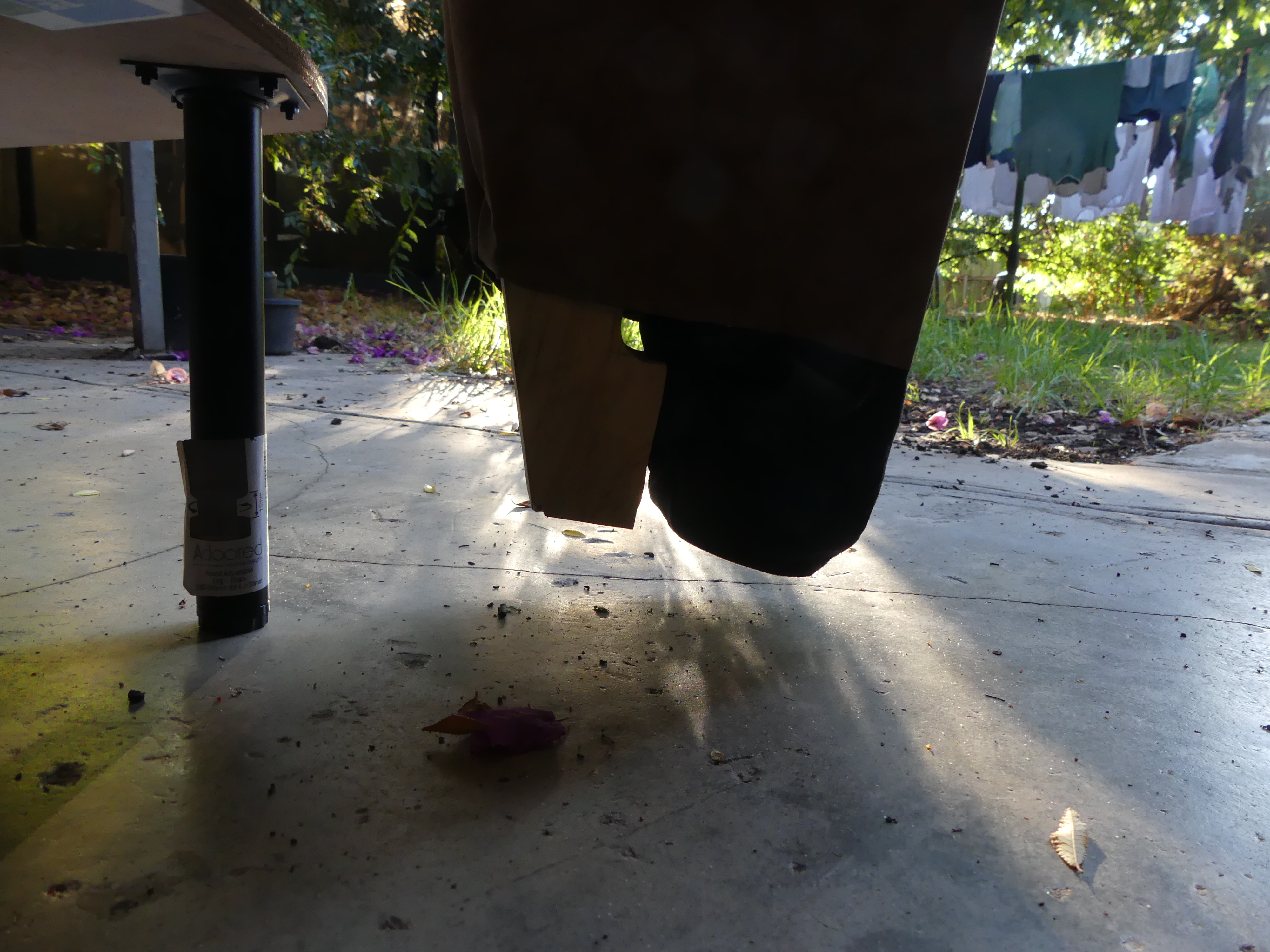
No eating the concrete, Mr. Mechanical Horse!
Anyway, that's that for now. Next step here is to add those cheek sensors, and also a means of measuring the rotation position of the head. I plan to do that super simple and yet super effective by strapping a cheap optical computer mouse to the underside of the neck, so that I can just read the mouse position to get the rotational position. The rate of movement combined with the cheek sensors should indicate the sideways pressure from providing an open rein aid to the "horse". But that will have to wait for the next post.


Comments
Post a Comment